Dear Mr. Electrician: I need to see some three-point switch wiring diagrams. I possess two switches that control one light in my kitchen. I am not sure if they are 3-fashio switches or 2-way light switches. I find that one switch has to stay in the up position at all times with great care the other switch will turn on the Inner Light. How do I diagnose and fix this?
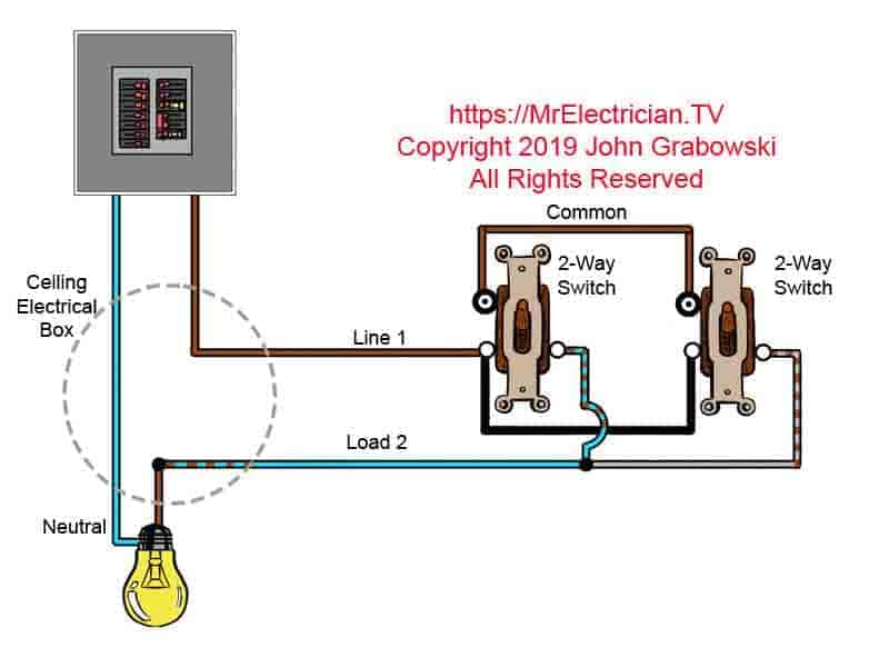
Answer: This blog post has a few different deuce-ac-way flip wiring diagrams on with some good advice. One diagram is above, the rest are below. NOTE: Whatsoever text links below rifle to applicable products along Amazon. As an Amazon River Associate I earn from passing purchases.
Two-way physical phenomenon light switches and 3-way light switches are the one thing, they just now have different names according to country. I am guessing that incomparable of your three-style switches stone-broke down.
Shut off the physical phenomenon power for the circuit at the circuit breaker box. Due to fivefold wires being hot in this particular type of switch wiring IT can embody a pocket-sized tricky for an recreational to diagnose which 3-way switch failed.
Assuming that the 3-way switches were wired correctly, I suggest that you switch 1 switch. If that doesn't fix information technology, and then convert the other one.
I unremarkably take cardinal telegram off the old switch at a sentence and put information technology along the young switch then double with the past wires. Please note the other color screw terminals. It's a good idea to supervene upon both switches concurrently A the past one could go wrong presently subsequently.
If the 3-right smart switches were not correctly bugged, then you must be very careful to identify the LINE and LOAD wires In front you disconnect the switches. LINE is the power and Shipment goes to the light or other things obsessed by the 3-ways.
The LINE wire bequeath be live (Hot) with electricity at every last multiplication regardless of the 3-right smart switch positions which makes IT the easiest to identify. Use a voltage tester with deuce leads operating theater a pigtail light socket with an incandescent or halogen light electric light.
Non-contact voltage testers may give you false readings due to the close proximity of the wires on the alternate. It is top-quality to hit the suspected hot wire from the screw terminal to test information technology with a non-contact voltage sensing element.
Wear insulated electrical gloves when functioning with live electric circuits.
Click here for my blog post about working around your home safely.
Do non remove all of the wires from the one leash-way trade now and so try and figure what each wire is. First thing is to take notice of the color of the screw terminals on the old switch.
One jazz end testament be a different color than the separate cardinal screw terminals and wish be tagged "Common" (See exposure under). That screw should have either a LINE wire or a LOAD telegram connected to it.
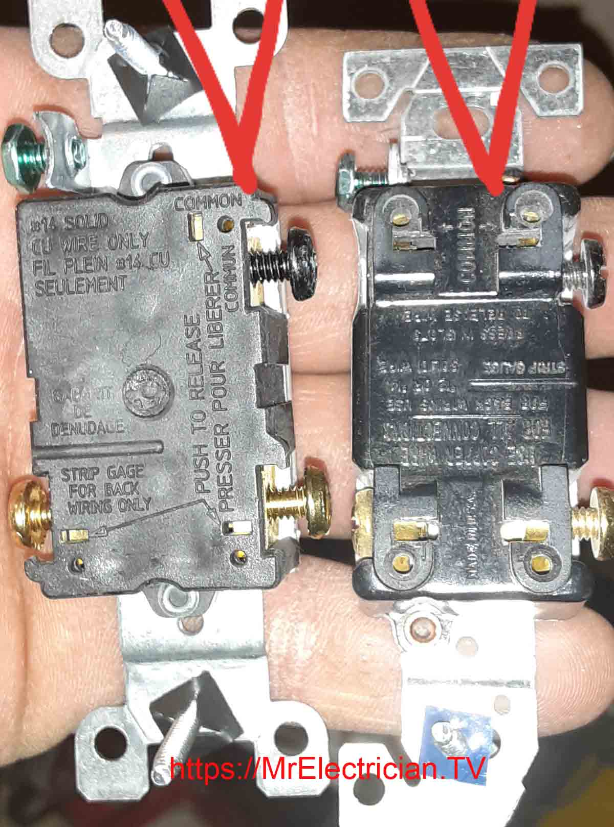
Thank you to John S. for the above photo depicting the common terminals on triangular switches. The common terminals are the ones with the different colouring used for LINE and LOAD. The unlabeled brass terminal screws are for the traveler wires to get connected to.
You cannot swear entirely on the wire people of color coding on threesome-means switch wiring diagrams to figure out what each wire's function is in an existing 3-way switch installation. The original installers used whatever materials and wiring methods were acceptable at the metre of installation. It is optimal to identify the LINE and the LOAD wires.
There are old existing 3-way electric switch installations that arrange non follow acceptable industry practice or physical phenomenon code requirements. That is wherefore it is important to identify the function of the wires for 3-way electric light switches.
Changing a 3-way switch to a WiFi smart switch can follow tricky. You will need a white neutral conductor to force the sharp switch. You cannot use the bare or Green River grounding conductor or else of a amoral. In addition some changes may need to be made at the other 3-room switch in the circuit.
Most likely the LOAD and indefinite traveler bequeath motivation to represent connected together while the other traveller is capped with a wire connector. Every fast switch volition cost different and you must take after the manufacturer's facility instructions.
Before buying a cagy switch I suggest that you check the manufacturers website for the installation book of instructions. Read the instructions before buying the intense switch.
COMPONENTS OF Three-point switch WIRING
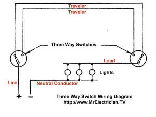
Completely three-way switch and 2-way alternate wiring diagrams have the same BASIC components: Wires consisting of a LINE, a LOAD, a neutral, a pair of travelers, and two 3-manner switches. If you are trying to troubleshoot a 3-way switch operation, you will need to identify the function of each wire. Do this before you disconnect whatsoever wires from the switches.
The Phone line wire is usually the easiest to identify because it is live (Hot) at all times. It should make up terminated along a vulgar Cu Oregon black screw on one of the 3-way switches. The else three-point switch will have the LOAD wire connected to the common copper or pitch blackness screw. A voltage tester is best for testing the live wires with unreactive and/or solid ground ground.
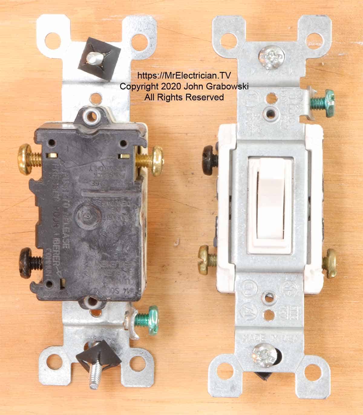
Note the unrivaled black screw on each of the higher up three-way switches. Only the LOAD wire operating room the LINE wire gets concluded on the common Shirley Temple screw. The green screw is only for grounding purposes and essential have only one establish wire wired thereto.
Click Here to see all of the Three-Manner Switches Forthcoming on Virago
It is possible to simply replace the switches without having to key the mathematical function of each conductor. In this case you would just remove one wire at a meter and lay out it on the same terminal on the new switch. Submit note of the vividness of the screw terminals along the old and the new switches. Check the rear of the old switch over for the "Common" terminal.
With older wires where the colour is not very distinguishable, I use colored electric tape to identify the conductors. It is real helpful and makes replacement a great deal easier the next metre the switches need to be changed. I always have blacken, white, red, green, and blue physical phenomenon tape happening my truck.
'tween each many-sided switch is a pair of "Travelers" that are connected to the unlabeled brass terminals. The traveler wires are interchangeable between the two brass neutral-colored terminal screws.
On single of the 3-manner switches a LINE OR hot telegram gets connected to the common cop or Shirley Temple Black screw terminal. On the other three-mode switch the Load up wire (The LOAD is the wire that feeds power to the light fixture) gets connected to the familiar copper or black sleep with terminal.
Below is a cuneate three-right smart schematic that behind be practical to each deuce-ac-way electrical light switch connections. This is single a wiring schematic and not the true wiring method acting used for 3-way switch installations.
More iii-way switch wiring diagrams depicting genuine wiring methods are further down.
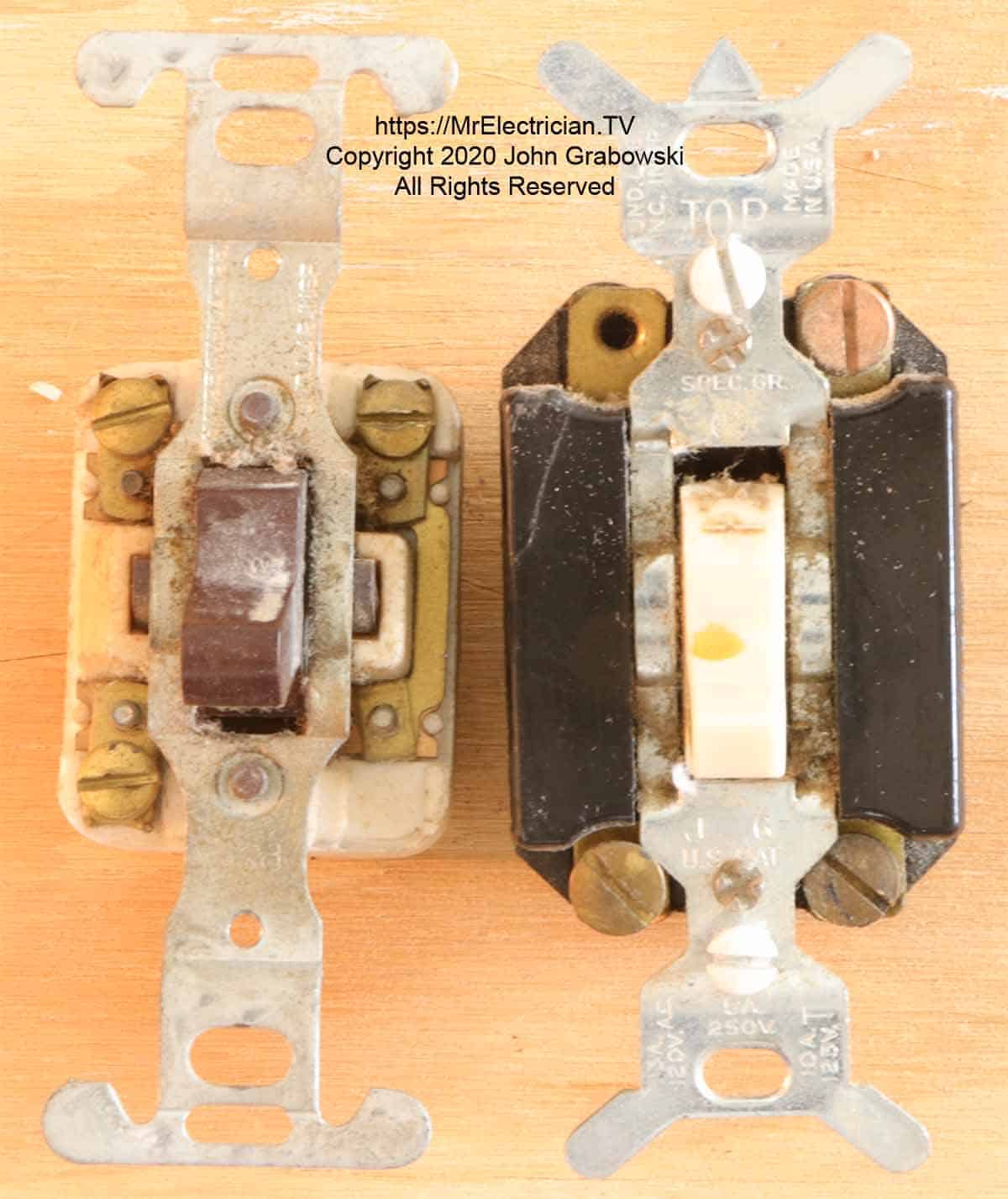
Two very nonagenarian troika-way switches are delineated in the photo above. The bang terminals were on the front of switches some, many old age ago. This was unsafe having live physical phenomenon terminals so close to a tinny wall plate. I have in person seen a few instances where the metal wall plate was coming in get hold of with the live terminals and creating a short electric circuit resulting in a tripped circuit breaker.
Thomas More Three-point switch WIRING DIAGRAMS
There are single trio-way switch wiring methods that can be victimized and it is usually the installer that determines what is the best way of life for his OR her purposes. In around countries the three-way switch is called a two-way switch.
The Home Electric Write in coderequires that a neutralised conductor (White wire) be installed at virtually new light switch locations however article 404-2(C) only requires the objective at one 3-way switch location.
The three way switch wiring plot depicted at the top of this post is probably the most common method for wiring three-way of life switches. The deuce-telegram LINE cable goes into single switch box and the two-cable LOAD cable goes into the other switch box. A 3 conductor cable with a groundis then installed between the cardinal 3-way interchange boxes.
This method is also code compliant with consider to package take and the number of wires that each electrical box is limited to having inside.
At the LINE switch box seat, the black wire of the ii wire LINE cable gets connected to the common copper operating theatre black screw concluding on the three-way of life switch. The red and dirty wires (Travelers) of the 3-wire cable sire connected to the brass terminals on the three-point switch. It doesn't weigh which traveler goes on which brass terminal.
The white LINE neutral wire gets connected to the white wire of the 14/3 cable. At the separate end the white LOAD neutral is connected to the white wire of the 14/3 cable. At the LOAD switch box, the calamitous wire of the two-wire LOAD cable gets connected to the park copper or black terminal on the three-way switch. The whiten LOAD telegram gets connected to the white wire of the three-wire cable. The red and black travelers in the 3-wire cable get connected to the brass instrument terminals on the ternary-mode switch.
The above method is good because it ensures that the white LINE inert director is lendable at each substitution box. In addition this method requires only a 3 music director cable (With ground) betwixt the switches.
Not every existing 3-way flip installation has the same wire colors. It is important to identify the LINE and Lode wires before replacing 3-way and 2-path light switches. Take notice which wires are adjunctive to the communal atomic number 29 or sarcastic screw terminals.
A variant of the above three-way and 2-Way switch wiring is to impart all of the cables into one palisade interchange box arsenic represented in the diagram infra, and branch off from on that point to each switch and light fixture.
The LINE and LOAD are brought into one 3-style switch electrical box. From at that place a 3-wire cable (2 travelers, a land, and the re-identified clean telegram) Beaver State a conduit would need to be installed over to the second 3-way switch.
Whenever the white cable is being used as something other than the neutral music director it must be changed to a different colouring. This is accomplished with colored electrical tape or a permanent wave ink marking pen.
At the second 3-way switch, the fatal wire would be connected on the common copper or black screw terminal connected the switch.
The bare operating theatre green wire is contiguous to the gilded switch box with a 10/32 machine have it off, and onto the green screw on the 3-way switch. The bare operating theatre green grounding conductor is non shown in these wiring diagrams systematic to dungeon them simple.
Mouse click Hera to meet my blog post roughly wall plug and switch foundation.
The electric box must be big enough to accommodate the number of wires. See Article 314 in the National Electrical Code (NFPA 70) for electric box infinite requirements.
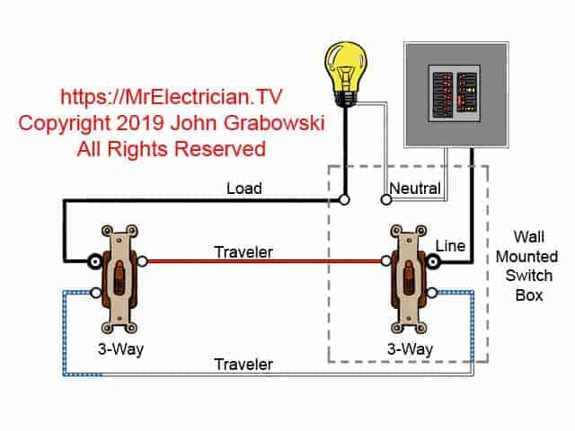
In the above diagram the white wire must be re-known with a different color at each switch location. The albescent wire betwixt switches is not being secondhand as a neutral, it is a traveler and cannot be white.
Use unfair electrical magnetic tape opposite than red or black, or a permanent ink marker playpen to change the wire color. The photo below is an example of the LINE and Incumbrance in the same switch loge.
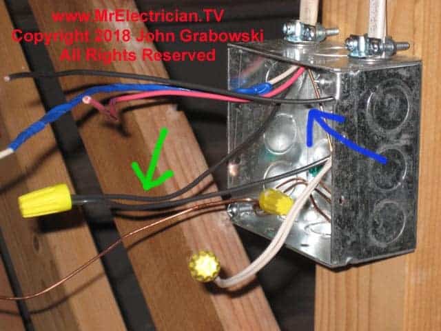
In the photo above the Green River arrow points to the Transmission line hot electrify connected to the black wire of the 14/3 wire that is going to the other 3-way flip-flop. The blue pointer points to the LOAD wire which will be coupled onto the popular black or red lead-colored depot on the 3-way light replacement to be installed in this box.
The red and puritanic wires in this installation are the travelers. This was added to an existing installation that only had one single pole wall switch at the big top of the basement stairs for the cellar lights. The homeowner wanted an additional switch in the basement.
The pic below shows the wiring at the other 3-Room location which was a single pole replacement originally.
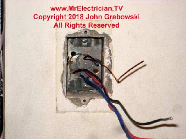
The black hot telegram in the electrical box above is connected at the other end to the black LINE wire and gets connected to the common black or red piece of tail on the 3-right smart tack. The Stanford White wire has been taped with blue electrical videotape to show that it is non a neutral conductor, but a traveller. The red electrify is the other traveller. The travelers produce connected to the two organisation screw terminals along the 3-way switch.
When a white cable is being used as a traveler, it needs to receive its coloring material changed reported to Article 310.110(C). Whatever color but white, intermediate, or green hindquarters Be victimized. The extra clamp at the top of this alternate box needs to be removed atomic number 3 information technology counts American Samoa one additional wire (Article 314.16(B)(2).
At the first switch over box, the illegal wire that was run to the second 3-way switch can be engaged to either the dim LOAD cable OR the colored LINE wire. The black Describe wire or LOAD wire that is non connected to the second 3-way switch, gets connected onto the common pig or black terminus of the first 3-way electric switch.
The LINE and Warhead white neutral wires should be spliced together. The traveler wires from the second switch get joined to the synoptical two brass terminals on the first switch over.
The ground wires should altogether be joined together and one surgery two pigtails attached from that bunch should live connected to the metal box with a 10/32 machine screw and to the green have sex terminal on the 3-fashio switch.
Another example of an alternative 3-way wiring method is to bring all of the cables into the ceiling light fixture electrical box. From there a three conductor cable's length or a conduit would need to be installed to one of the 3-direction substitution locations. A four music director cable with priming coat or a conduit would necessitate to be installed to the unusual 3-mode switch location pro re nata by code to have a white unreactive conductor in peerless of the flip boxes.
A larger ceiling electrical corner would be needed to accommodate all of the wires in this especial 3-way substitution installation. A lower limit of 24 cubic inches is required if #14 wire is used. Control Tables 314.16(A) & (B). Two cubic inches are obligatory for to each one #14 wire.
An update in the 2022 National Electrical Code requires that all ceiling ablaze electrical boxes where a ceiling fan could perhaps be installed must be rated forceiling fan back. See article 314.27(C).
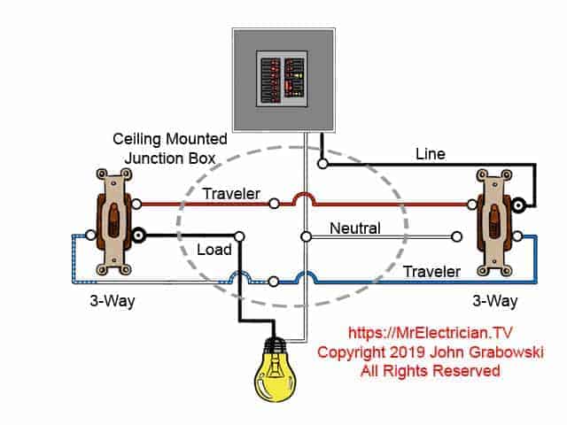
At each switch in the above 3-way switch wiring diagram the black wire gets associated to the common atomic number 29 or fatal screw. In the ceiling light fixture electric box, one Afro-American wire from a 3-way switch gets linked to the black Lade electrify on the autofluorescent fixture. The unfortunate wire from the other 3-style gets connected to the LINE black wire. The Logical argument white neutral conducting wire gets connected to the light fix.
The travelers in the ceiling light junction box engender spliced through color to colouration. The grounds are connected in collaboration, to the metal box, and also to the light fix. The ceiling physical phenomenon junction box needs to be extra large to suit all of the wires. Observe of the white neutral wire that is required to be in one of the switch boxes.
In the UK some electricians use an alternative method for wiring two-way switches equally delineate in the above wiring plot. Two-agency switches and three-agency switches operate the same way and have the same connectedness points, they retributory undergo variant name calling in the UK which are Common, L1, and L2.
The above electric switch wiring plot shows a different wire color coding than what is victimized in the USA. In this wiring configuration the Common terminals on all 2-style switch are connected unneurotic with one wire. The LINE wire is attached to the L1 terminal and the Lade wire is connected to the L2 terminal.
If you wanted to add more switches you would instal four-way switches, or as they are called in Europe, intermediate switches which get wired to the L1 and L2 wires. The average switches are wired in between the cardinal-ways. Using a three core cable, the Common wire going to the 2-way switches sporting passes through each halfway shift physical phenomenon boxwood. Colored electrical tape is used to re-identify the wires.
The ground wires are not shown on these diagrams to save space and play easy viewing. However during the initiation, all ground wires would be joined together and a pigtail for each switch would be added. All bimetal electrical boxes postulate earthing with its own earthing pigtail victimisation a 10/32 machine screw propeller in the back of the box.
You might determine my postal service depicting 4-Way switch wiring diagrams helpful.
If you are preparation to install a ceiling fan, travel to my blog post depicting ceiling rooter wiring diagrams for additive counselling.
For man-to-man pole light switch wiring diagrams check my post here.
To wire wall in switches to control electrical outlets, see my post present.
Panasonic Whisper Green With Light Switch and Fan Switch Wiring Diagram
Source: https://mrelectrician.tv/three-way-switch-wiring-diagrams/


0 Komentar
Post a Comment